26. Drawing Shapes
Learn to draw various 2D shapes available in Siv3D.
26.1 Circle
- Circles are represented by the
Circle class
Circle can be created as follows:
- Behavior is undefined when the radius is negative
| Code |
Description |
Circle{ X coordinate, Y coordinate, radius } |
Creates a circle from center coordinates and radius |
Circle{ center coordinates, radius } |
Creates a circle from center coordinates and radius |
point.asCircle(radius) |
Creates a circle using a Point value as the center with specified radius |
vec2.asCircle(radius) |
Creates a circle using a Vec2 value as the center with specified radius |
- To draw a circle, use
Circle's .draw()
| Code |
Description |
.draw(color) |
Draws a circle |
.draw(inner color, outer color) |
Draws a gradient circle |
# include <Siv3D.hpp>
void Main()
{
Scene::SetBackground(ColorF{ 0.6, 0.8, 0.7 });
while (System::Update())
{
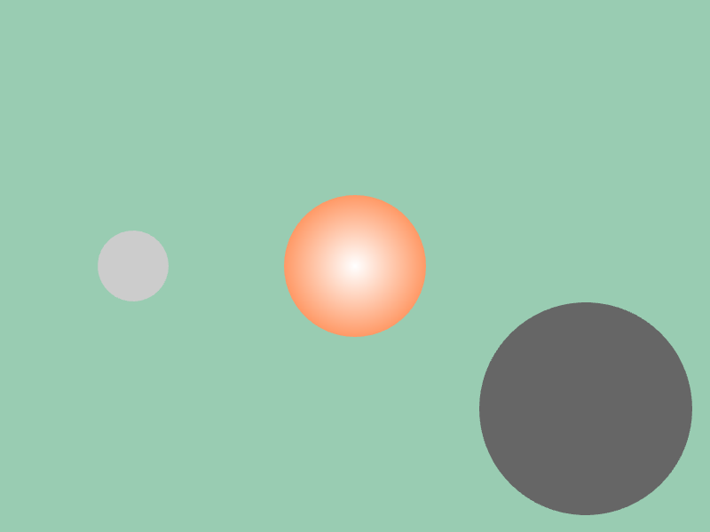
Circle{ 150, 300, 40 }.draw(ColorF{ 0.8 });
Circle{ Vec2{ 400, 300 }, 80 }.draw(ColorF{ 1.0 }, ColorF{ 1.0, 0.6, 0.4 });
Cursor::Pos().asCircle(120).draw(ColorF{ 0.4 });
}
}
26.2 Circle Outline
- To draw a circle outline, use
Circle's .drawFrame()
- Behavior is undefined when thickness is outside the normal range (e.g., negative)
| Code |
Description |
.drawFrame(thickness, color) |
Draws a circle outline |
.drawFrame(thickness, inner color, outer color) |
Draws a gradient circle outline |
.drawFrame(inner thickness, outer thickness, color) |
Draws a circle outline |
.drawFrame(inner thickness, outer thickness, inner color, outer color) |
Draws a gradient circle outline |
- Since
.draw() and .drawFrame() return a reference to the circle itself, you can chain them like circle.draw().drawFrame()
# include <Siv3D.hpp>
void Main()
{
Scene::SetBackground(ColorF{ 0.6, 0.8, 0.7 });
while (System::Update())
{
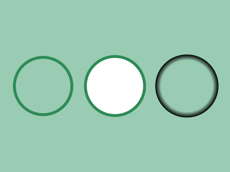
Circle{ 150, 300, 100 }.drawFrame(10, Palette::Seagreen);
Circle{ 400, 300, 100 }.draw().drawFrame(2, 8, Palette::Seagreen);
Circle{ 650, 300, 100 }.drawFrame(20, ColorF{ 0.0, 0.0 }, ColorF{ 0.0, 1.0 });
}
}
26.3 Pie Shape
- To draw a pie shape, use
Circle's .drawPie()
- The start angle is specified in clockwise radians, with 0 being at 12 o'clock
- The pie angle is specified as the angular size in the clockwise direction
- If negative, the pie is drawn counterclockwise
| Code |
Description |
.drawPie(start angle, pie angle, color) |
Draws a pie shape |
.drawPie(start angle, pie angle, inner color, outer color) |
Draws a gradient pie shape |
# include <Siv3D.hpp>
void Main()
{
Scene::SetBackground(ColorF{ 0.6, 0.8, 0.7 });
while (System::Update())
{
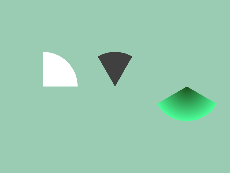
Circle{ 150, 300, 120 }.drawPie(0_deg, 90_deg, ColorF{ 1.0 });
Circle{ 400, 300, 120 }.drawPie(-30_deg, 60_deg, ColorF{ 0.25 });
Circle{ 650, 300, 120 }.drawPie(120_deg, 120_deg, ColorF{ 0.1, 0.3, 0.1 }, ColorF{ 0.3, 1.0, 0.6 });
}
}
26.4 Arc
- To draw an arc, use
Circle's .drawArc()
- The start angle is specified in clockwise radians, with 0 being at 12 o'clock
- The arc angle is specified as the angular size in the clockwise direction
- If negative, the arc is drawn counterclockwise
- Behavior is undefined when thickness is outside the normal range (e.g., negative)
| Code |
Description |
.drawArc(start angle, arc angle, inner thickness, outer thickness, color) |
Draws an arc |
.drawArc(start angle, arc angle, inner thickness, outer thickness, inner color, outer color) |
Draws a gradient arc |
.drawArc(LineStyle::RoundCap, start angle, arc angle, inner thickness, outer thickness, color) |
Draws an arc with rounded ends |
# include <Siv3D.hpp>
void Main()
{
Scene::SetBackground(ColorF{ 0.6, 0.8, 0.7 });
while (System::Update())
{
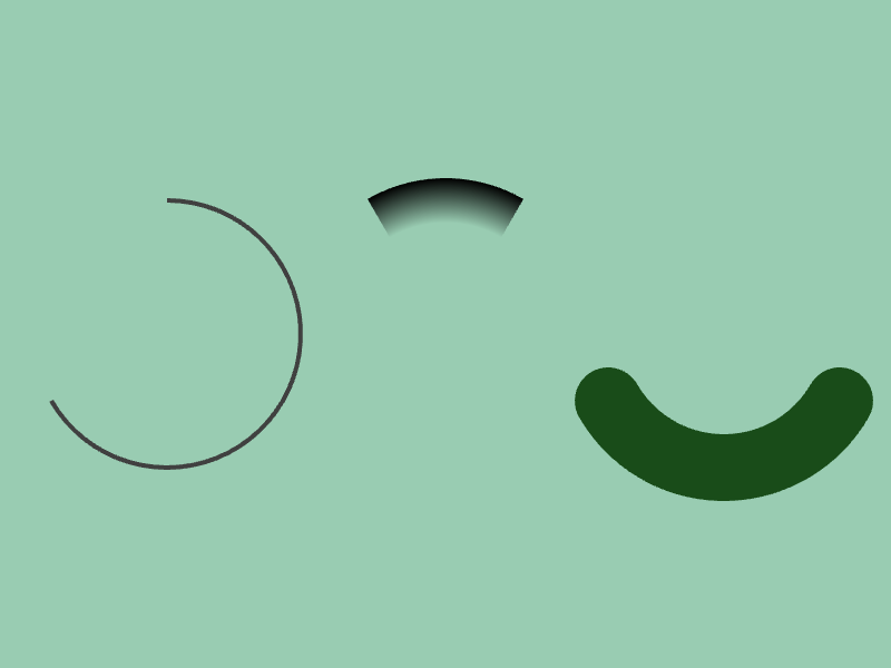
Circle{ 150, 300, 120 }.drawArc(0_deg, 240_deg, 2, 2, ColorF{ 0.25 });
Circle{ 400, 300, 120 }.drawArc(-30_deg, 60_deg, 20, 20, ColorF{ 0.0, 0.0 }, ColorF{ 0.0, 1.0 });
Circle{ 650, 300, 120 }.drawArc(LineStyle::RoundCap, 120_deg, 120_deg, 30, 30, ColorF{ 0.1, 0.3, 0.1 });
}
}
26.5 Circle Segment
- To draw a circle segment (chord), use
Circle's .drawSegment() or .drawSegmentFromAngles()
- Angles are specified in radians
| Code |
Description |
.drawSegment(center direction of arc, arc angle, color) |
Draws a circle segment |
.drawSegment(arc start angle, arc angle, color) |
Draws a circle segment |

# include <Siv3D.hpp>

void Main()
{
	Scene::SetBackground(ColorF{ 0.6, 0.8, 0.7 });

	while (System::Update())
	{
		Circle{ 150, 200, 120 }.drawSegment(0_deg, 60, ColorF{ 0.9 });

		Circle{ 400, 200, 120 }.drawSegment(30_deg, 60, ColorF{ 0.9 });

		Circle{ 650, 200, 120 }.drawSegment(60_deg, 60, ColorF{ 0.9 });


		Circle{ 150, 400, 120 }.drawSegment(120_deg, 60, ColorF{ 0.25 });

		Circle{ 400, 400, 120 }.drawSegmentFromAngles(60_deg, 240_deg, ColorF{ 0.25 });

		Circle{ 650, 400, 120 }.drawSegmentFromAngles(90_deg, 120_deg, ColorF{ 0.25 });
	}
}
26.6 Rectangle
- Rectangles are represented by
Rect or RectF
Rect represents coordinates and sizes with int32 type, while RectF uses double type- You can use
Size type (alias for Point) and SizeF type (alias for Vec2) to represent sizes
- Rectangles can be created as follows:
- Behavior is undefined when width and height are negative
| Code |
Description |
Rect{ width, height }
RectF{ width, height } |
Creates a rectangle with top-left at (0, 0) |
Rect{ width and height }
RectF{ width and height } |
Creates a rectangle with top-left at (0, 0) |
Rect{ side length }
RectF{ side length } |
Creates a square with top-left at (0, 0) |
Rect{ top-left X, top-left Y, width, height }
RectF{ top-left X, top-left Y, width, height } |
Creates a rectangle |
Rect{ top-left X, top-left Y, width and height }
RectF{ top-left X, top-left Y, width and height } |
Creates a rectangle |
Rect{ top-left X, top-left Y, side length }
RectF{ top-left X, top-left Y, side length } |
Creates a square |
Rect{ top-left coordinates, width, height }
RectF{ top-left coordinates, width, height } |
Creates a rectangle |
Rect{ top-left coordinates, width and height }
RectF{ top-left coordinates, width and height } |
Creates a rectangle |
Rect{ top-left coordinates, side length }
RectF{ top-left coordinates, side length } |
Creates a square |
Rect{ Arg::center(center coordinates), width, height }
RectF{ Arg::center(center coordinates), width, height } |
Creates a rectangle by specifying center coordinates |
Rect{ Arg::center(center coordinates), width and height }
RectF{ Arg::center(center coordinates), width and height } |
Creates a rectangle by specifying center coordinates |
Rect{ Arg::center(center coordinates), side length }
RectF{ Arg::center(center coordinates), side length } |
Creates a square by specifying center coordinates |
Rect::FromPoints(corner coordinates, diagonal corner coordinates)
RectF::FromPoints(corner coordinates, diagonal corner coordinates) |
Creates a rectangle from two given points.
A valid rectangle with positive size is created |
- To draw a rectangle, use
Rect or RectF's .draw()
| Code |
Description |
.draw(color) |
Draws a rectangle |
.draw(Arg::top = top color, Arg::bottom = bottom color) |
Draws a vertical gradient rectangle |
.draw(Arg::left = left color, Arg::right = right color) |
Draws a horizontal gradient rectangle |
.draw(Arg::topLeft = top-left color, Arg::bottomRight = bottom-right color) |
Draws a diagonal gradient rectangle from top-left to bottom-right |
.draw(Arg::topRight = top-right color, Arg::bottomLeft = bottom-left color) |
Draws a diagonal gradient rectangle from top-right to bottom-left |
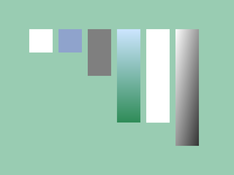
# include <Siv3D.hpp>

void Main()
{
	Scene::SetBackground(ColorF{ 0.6, 0.8, 0.7 });

	while (System::Update())
	{
		Rect{ 100, 100, 80 }.draw();

		RectF{ Vec2{ 200, 100 }, 80 }.draw(HSV{ 220, 0.3, 0.8 });

		Rect{ 300, 100, 80, 160 }.draw(ColorF{ 0.5 });

		Rect{ Point{ 400, 100 }, Size{ 80, 320 } }.draw(Arg::top(0.8, 0.9, 1.0), Arg::bottom = Palette::Seagreen);

		RectF{ 500, 100, SizeF{ 80.0, 320.5 } }.draw();

		Rect{ 600, 100, 80, 400 }.draw(Arg::topLeft(1.0), Arg::bottomRight(0.2));
	}
}
26.7 Rectangle Outline
- To draw a rectangle outline, use
Rect or RectF's .drawFrame()
- Behavior is undefined when thickness is outside the normal range (e.g., negative)
| Code |
Description |
.drawFrame(thickness, color) |
Draws a rectangle outline |
.drawFrame(thickness, inner color, outer color) |
Draws a gradient rectangle outline |
.drawFrame(inner thickness, outer thickness, color) |
Draws a rectangle outline |
.drawFrame(inner thickness, outer thickness, inner color, outer color) |
Draws a gradient rectangle outline |
.drawFrame(thickness, Arg::top = top color, Arg::bottom = bottom color) |
Draws a vertical gradient rectangle outline |
.drawFrame(inner thickness, outer thickness, Arg::top = top color, Arg::bottom = bottom color) |
Draws a vertical gradient rectangle outline |
- Since
.draw() and .drawFrame() return a reference to the rectangle itself, you can chain them like rect.draw().drawFrame()
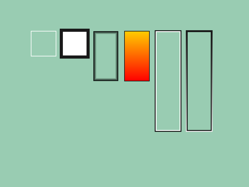
# include <Siv3D.hpp>

void Main()
{
	Scene::SetBackground(ColorF{ 0.6, 0.8, 0.7 });

	while (System::Update())
	{
		Rect{ 100, 100, 80 }.drawFrame(2);

		Rect{ 200, 100, 80 }
			.draw()
			.drawFrame(2, 8, ColorF{ 0.1 });

		Rect{ 300, 100, 80, 160 }.drawFrame(10, 0, ColorF{ 0.0, 0.0 }, ColorF{ 0.0, 1.0 });

		Rect{ 400, 100, 80, 160 }
			.draw(Arg::top(1.0, 0.8, 0.0), Arg::bottom = Palette::Red)
			.drawFrame(2, ColorF{ 0.1 });

		Rect{ 500, 100, 80, 320 }
			.drawFrame(3, 0)
			.drawFrame(0, 3, ColorF{ 0.1 });

		Rect{ 600, 100, 80, 320 }
			.drawFrame(3, 0, ColorF{ 0.1 })
			.drawFrame(0, 3, Arg::top(0.1), Arg::bottom(0.9));
	}
}
26.8 Rounded Rectangle
- Rounded rectangles are represented by
RoundRect
RoundRect can be created as follows:
- Behavior is undefined when size is negative or corner radius is invalid
| Code |
Description |
RoundRect{ top-left X, top-left Y, width, height, corner radius } |
Creates a rounded rectangle |
RoundRect{ top-left coordinates, width, height, corner radius } |
Creates a rounded rectangle |
RoundRect{ top-left coordinates, width and height, corner radius } |
Creates a rounded rectangle |
RoundRect{ Rect{ ... }, corner radius } |
Creates a rounded rectangle |
RoundRect{ RectF{ ... }, corner radius } |
Creates a rounded rectangle |
RoundRect{ Arg::center(center coordinates), width, height, corner radius } |
Creates a rounded rectangle by specifying center coordinates |
RoundRect{ Arg::center(center coordinates), width and height, corner radius } |
Creates a rounded rectangle by specifying center coordinates |
rect.rounded(corner radius) |
Creates a rounded rectangle from a rectangle (Rect or RectF) |
- To draw a rounded rectangle, use
RoundRect's .draw()
| Code |
Description |
.draw(color) |
Draws a rounded rectangle |
.draw(Arg::top = top color, Arg::bottom = bottom color) |
Draws a vertical gradient rounded rectangle |
- To draw a rounded rectangle outline, use
RoundRect's .drawFrame()
| Code |
Description |
.drawFrame(thickness, color) |
Draws a rounded rectangle outline |
.drawFrame(inner thickness, outer thickness, color) |
Draws a rounded rectangle outline |
.drawFrame(thickness, Arg::top = top color, Arg::bottom = bottom color) |
Draws a vertical gradient rounded rectangle outline |
.drawFrame(inner thickness, outer thickness, Arg::top = top color, Arg::bottom = bottom color) |
Draws a vertical gradient rounded rectangle outline |

# include <Siv3D.hpp>

void Main()
{
	Scene::SetBackground(ColorF{ 0.6, 0.8, 0.7 });

	const Rect rect{ 100, 300, 500, 200 };

	while (System::Update())
	{
		RoundRect{ 100, 100, 200, 100, 20 }.draw();

		RoundRect{ Arg::center(600, 150), 200, 80, 10 }.draw();

		rect.rounded(40).draw(ColorF{ 0.2 });
	}
}
26.9 Rectangle with Some Rounded Corners
- There is no dedicated class for rectangles with partially rounded corners; they are represented using the general polygon class
Polygon
- A
Polygon representing a rectangle with some rounded corners can be created as follows:
- Behavior is undefined when curve radius is invalid
| Code |
Description |
rect.rounded(tl, tr, br, bl) |
Creates a rectangle with some rounded corners from a rectangle (Rect or RectF) |
tl is the top-left corner radius, tr is the top-right corner radius, br is the bottom-right corner radius, and bl is the bottom-left corner radius- To draw a rectangle with some rounded corners, use
Polygon's .draw()
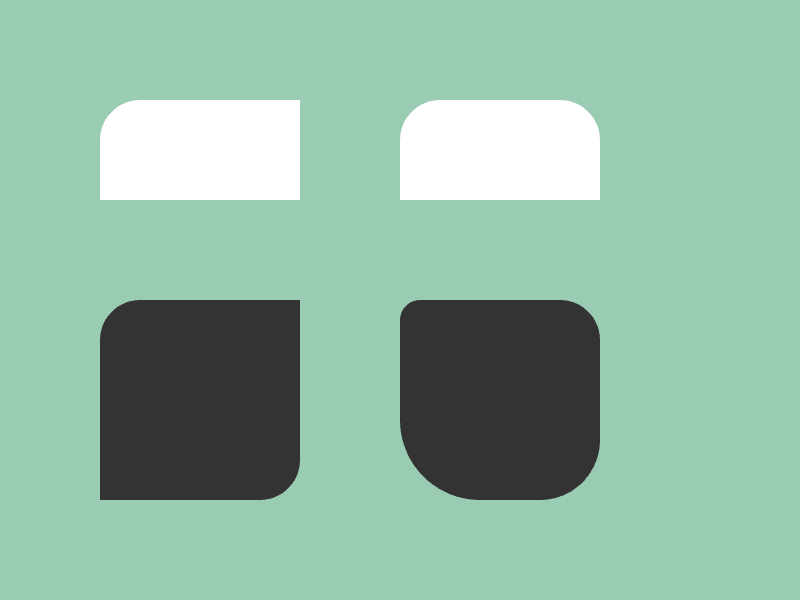
# include <Siv3D.hpp>

void Main()
{
	Scene::SetBackground(ColorF{ 0.6, 0.8, 0.7 });

	while (System::Update())
	{
		Rect{ 100, 100, 200, 100 }
			.rounded(40, 0, 0, 0).draw();

		Rect{ 400, 100, 200, 100 }
			.rounded(40, 40, 0, 0).draw();

		Rect{ 100, 300, 200, 200 }
			.rounded(40, 0, 40, 0).draw(ColorF{ 0.2 });

		Rect{ 400, 300, 200, 200 }
			.rounded(20, 40, 60, 80).draw(ColorF{ 0.2 });
	}
}
26.10 Line Segment
- Line segments are represented by
Line
Line can be created as follows:
| Code |
Description |
Line{ start X, start Y, end X, end Y } |
Creates a line segment |
Line{ start coordinates, end coordinates } |
Creates a line segment |
Line{ start, end X, end Y } |
Creates a line segment |
Line{ start X, start Y, end } |
Creates a line segment |
Line{ start X, start Y, Arg::angle = direction, length } |
Creates a line segment |
Line{ start coordinates, Arg::angle = direction, length } |
Creates a line segment |
Line{ start X, start Y, Arg::direction = direction vector } |
Creates a line segment |
Line{ start coordinates, Arg::direction = direction vector } |
Creates a line segment |
rect.top(), rect.bottom(), rect.left(), rect.right() |
Creates line segments representing the
top, bottom, left, or right edge of a rectangle (Rect or RectF) |
- To draw a line segment, use
Line's .draw()
| Code |
Description |
.draw(color) |
Draws a line segment |
.draw(start color, end color) |
Draws a gradient line segment |
.draw(thickness, color) |
Draws a line segment |
.draw(thickness, start color, end color) |
Draws a gradient line segment |
.draw(line style, thickness, color) |
Draws a line segment |
.draw(line style, thickness, start color, end color) |
Draws a gradient line segment |
- You can specify one of the following line styles:
| Code |
Description |
LineStyle::SquareCap |
Square ends (default) |
LineStyle::Uncapped |
Flat ends |
LineStyle::RoundCap |
Rounded ends |
LineStyle::SquareDot |
Square dotted line |
LineStyle::RoundDot |
Round dotted line |

# include <Siv3D.hpp>

void Main()
{
	Scene::SetBackground(ColorF{ 0.6, 0.8, 0.7 });

	while (System::Update())
	{
		Line{ 100, 100, 400, 150 }.draw(4);

		Line{ 400, 300, Cursor::Pos() }.draw(10, Palette::Seagreen);

		Line{ 100, 400, 700, 400 }.draw(12, Palette::Orange);

		Line{ 100, 450, 700, 450 }.draw(LineStyle::RoundCap, 12, ColorF{ 0.2 });

		Line{ 100, 500, 700, 500 }.draw(LineStyle::SquareDot, 12,  ColorF{ 0.2 });

		Line{ 100, 550, 700, 550 }.draw(LineStyle::RoundDot, 12,  ColorF{ 0.2 });
	}
}
- When drawing horizontal or vertical line segments, consider using
Rect or RectF
- Drawing as a rectangle is advantageous in terms of quality and performance
26.11 Arrow
- There is no dedicated class for arrows; use
Line's .drawArrow() or .drawDoubleHeadedArrow() to draw them
- Single-directional arrows are drawn from the
Line's start point toward the end point
| Code |
Description |
.drawArrow(line width, triangle width and height, color) |
Draws a single-directional arrow |
.drawDoubleHeadedArrow(line width, triangle width and height, color) |
Draws a double-headed arrow |
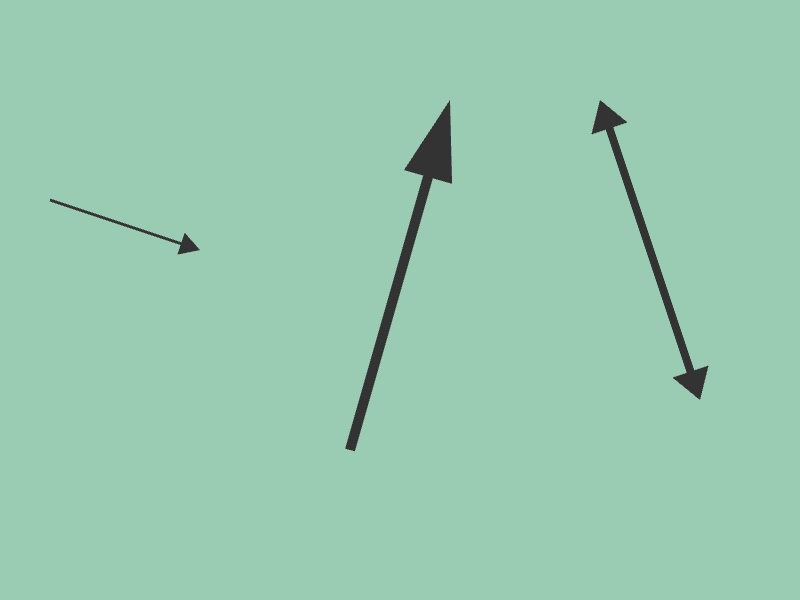
# include <Siv3D.hpp>

void Main()
{
	Scene::SetBackground(ColorF{ 0.6, 0.8, 0.7 });

	while (System::Update())
	{
		Line{ 50, 200, 200, 250 }
			.drawArrow(3, SizeF{ 20, 20 }, ColorF{ 0.2 });

		Line{ 350, 450, 450, 100 }
			.drawArrow(10, SizeF{ 40, 80 }, ColorF{ 0.2 });

		Line{ 600, 100, 700, 400 }
			.drawDoubleHeadedArrow(8, SizeF{ 30, 30 }, ColorF{ 0.2 });
	}
}
26.12 Triangle
- Triangles are represented by
Triangle
Triangle can be created as follows:
| Code |
Description |
Triangle{ side length } |
Creates an equilateral triangle with center at (0, 0) and specified side length |
Triangle{ side length, rotation angle } |
Creates a rotated equilateral triangle with center at (0, 0) and specified side length |
Triangle{ center X, center Y, side length } |
Creates an equilateral triangle with specified center and side length |
Triangle{ center coordinates, side length } |
Creates an equilateral triangle with specified center and side length |
Triangle{ center X, center Y, side length, rotation angle } |
Creates a rotated equilateral triangle with specified center and side length |
Triangle{ center coordinates, side length, rotation angle } |
Creates a rotated equilateral triangle with specified center and side length |
Triangle{ x0, y0, x1, y1, x2, y2 } |
Creates a triangle by specifying three vertices clockwise |
Triangle{ pos0, pos1, pos2 } |
Creates a triangle by specifying three vertices clockwise |
Triangle::FromPoints(pos0, pos1, pos2) |
Creates a triangle by specifying three vertices.
Vertex order is adjusted to create a valid triangle |
Note
- Triangles with vertices specified counterclockwise can be drawn but other features (collision detection, etc.) may not work correctly
- To draw a triangle, use
Triangle's .draw()
| Code |
Description |
.draw(color) |
Draws a triangle |
.draw(color0, color1, color2) |
Draws a triangle with specified colors for the three vertices |
- To draw a triangle outline, use
Triangle's .drawFrame()
| Code |
Description |
.drawFrame(thickness, color) |
Draws a triangle outline |
.drawFrame(inner thickness, outer thickness, color) |
Draws a triangle outline |
# include <Siv3D.hpp>
void Main()
{
Scene::SetBackground(ColorF{ 0.6, 0.8, 0.7 });
while (System::Update())
{
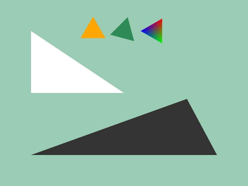
// Draw a triangle composed of coordinates (100, 100), (400, 300), (100, 300)
Triangle{ 100, 100, 400, 300, 100, 300 }.draw();
// Draw a triangle with center at (300, 100) and sides of 80px
Triangle{ 300, 100, 80 }.draw(Palette::Orange);
// Draw rotated 15° clockwise
Triangle{ 400, 100, 80, 15_deg }.draw(Palette::Seagreen);
// Draw rotated 30° clockwise
Triangle{ 500, 100, 80, 30_deg }.draw(HSV{ 0 }, HSV{ 120 }, HSV{ 240 });
// Specify three vertex coordinates with Point or Vec2 types
Triangle{ Cursor::Pos(), Vec2{ 700, 500 }, Vec2{ 100, 500 } }.draw(ColorF{ 0.2 });
}
}
26.13 Convex Quadrilateral
- Convex quadrilaterals with 4 vertices are represented by
Quad
- Trapezoids and parallelograms are represented by
Quad
- Unlike
Rect and RectF whose edges are parallel to the X and Y axes, Quad has no such constraint
Quad can be created as follows:
| Code |
Description |
Quad{ vertex0, vertex1, vertex2, vertex3 } |
Creates a quadrilateral by specifying four vertices |
Quad{ x0, y0, x1, y1, x2, y2, x3, y3 } |
Creates a quadrilateral by specifying four vertices |
Quad{ Rect{ ... } } |
Creates a quadrilateral from a rectangle |
Quad{ RectF{ ... } } |
Creates a quadrilateral from a rectangle |
rect.rotated(rotation angle) |
Creates a quadrilateral by rotating a rectangle (Rect or RectF) |
rect.rotatedAt(rotation center, rotation angle) |
Creates a quadrilateral by rotating a rectangle (Rect or RectF) |
rect.shearedX(slide distance) |
Creates a parallelogram by sliding the top and bottom edges of a rectangle (Rect or RectF) in the X direction |
rect.shearedY(slide distance) |
Creates a parallelogram by sliding the left and right edges of a rectangle (Rect or RectF) in the Y direction |
rect.skewedX(tilt angle) |
Creates a parallelogram by tilting the left and right edges of a rectangle (Rect or RectF) |
rect.skewedY(tilt angle) |
Creates a parallelogram by tilting the top and bottom edges of a rectangle (Rect or RectF) |
Note
- Behavior is undefined when the four vertices are counterclockwise or form a concave shape

- To draw a quadrilateral, use
Quad's .draw()
| Code |
Description |
.draw(color) |
Draws a quadrilateral |
.draw(color0, color1, color2, color3) |
Draws a quadrilateral with specified colors for the four vertices |
- To draw a quadrilateral outline, use
Quad's .drawFrame()
| Code |
Description |
.drawFrame(thickness, color) |
Draws a quadrilateral outline |
.drawFrame(inner thickness, outer thickness, color) |
Draws a quadrilateral outline |
26.13.1 Specifying 4 Vertices
- Create a
Quad by specifying four vertex coordinates
# include <Siv3D.hpp>
void Main()
{
Scene::SetBackground(ColorF{ 0.6, 0.8, 0.7 });
while (System::Update())
{
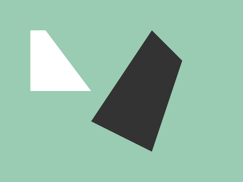
Quad{ Vec2{ 100, 100 }, Vec2{ 150, 100 }, Vec2{ 300, 300 }, Vec2{ 100, 300 } }.draw();
Quad{ 300, 400, 500, 100, 600, 200, 500, 500 }.draw(ColorF{ 0.2 });
}
}
26.13.2 Rotating a Rectangle
- Create a
Quad by rotating a rectangle

# include <Siv3D.hpp>

void Main()
{
	Scene::SetBackground(ColorF{ 0.6, 0.8, 0.7 });

	const Rect rect{ 150, 200, 400, 100 };

	double angle = 0_deg;

	while (System::Update())
	{
		angle += (Scene::DeltaTime() * 30_deg);

		rect.draw();

		// The center of the rectangle is the rotation axis
		rect.rotated(angle).draw(Palette::Seagreen);

		// The top-left of the rectangle is the rotation axis
		rect.rotatedAt(rect.pos, angle).draw(ColorF{ 0.2 });
	}
}
26.13.3 Sliding and Skewing a Rectangle
- Create a
Quad by sliding or skewing the edges of a rectangle
# include <Siv3D.hpp>
void Main()
{
Scene::SetBackground(ColorF{ 0.6, 0.8, 0.7 });
while (System::Update())
{
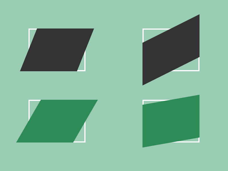
// Draw a parallelogram with edges slid 30px in the X direction
Rect{ 100, 100, 200, 150 }.drawFrame(4, 0)
.shearedX(30).draw(ColorF{ 0.2 });
// Draw a parallelogram with edges slid -50px in the Y direction
Rect{ 500, 100, 200, 150 }.drawFrame(4, 0)
.shearedY(-50).draw(ColorF{ 0.2 });
// Draw a parallelogram with left and right edges tilted 30°
Rect{ 100, 350, 200, 150 }.drawFrame(4, 0)
.skewedX(30_deg).draw(Palette::Seagreen);
// Draw a parallelogram with top and bottom edges tilted -10°
Rect{ 500, 350, 200, 150 }.drawFrame(4, 0)
.skewedY(-10_deg).draw(Palette::Seagreen);
}
}
26.14 Ellipse
- Ellipses are represented by
Ellipse
- Tilted ellipses cannot be represented.
- To draw a tilted ellipse, consider using
Transformer2D from Tutorial XX or approximating with Polygon
Ellipse can be created as follows:
| Code |
Description |
Ellipse{ center X, center Y, X-axis radius, Y-axis radius } |
Creates an ellipse |
Ellipse{ center coordinates, X-axis radius, Y-axis radius } |
Creates an ellipse |
Ellipse{ center X, center Y, X and Y-axis radius } |
Creates an ellipse |
Ellipse{ center coordinates, X and Y-axis radius } |
Creates an ellipse |
Ellipse{ Circle{ ... } } |
Creates an ellipse |
Ellipse{ Rect{ ... } } |
Creates an ellipse inscribed in a rectangle |
Ellipse{ RectF{ ... } } |
Creates an ellipse inscribed in a rectangle |
- To draw an ellipse, use
Ellipse's .draw()
| Code |
Description |
.draw(color) |
Draws an ellipse |
.draw(inner color, outer color) |
Draws a gradient ellipse |
- To draw an ellipse outline, use
Ellipse's .drawFrame()
| Code |
Description |
.drawFrame(thickness, color) |
Draws an ellipse outline |
.drawFrame(inner thickness, outer thickness, color) |
Draws an ellipse outline |

# include <Siv3D.hpp>

void Main()
{
	Scene::SetBackground(ColorF{ 0.6, 0.8, 0.7 });

	while (System::Update())
	{
		Ellipse{ 300, 200, 200, 100 }.draw();

		Ellipse{ 600, 400, 50, 150 }.draw(ColorF{ 0.2 });
	}
}
26.15 Common Shapes
- Functions are provided to draw commonly used shapes in a single line
- These functions return
Shape2D objects containing vertex arrays
| Code |
Shape |
Shape2D::Cross(radius, thickness, center = { 0, 0 }, rotation = 0.0) |
✖ mark |
Shape2D::Plus(radius, thickness, center = { 0, 0 }, rotation = 0.0) |
+ mark |
Shape2D::Pentagon(radius, center = { 0, 0 }, rotation = 0.0) |
Regular pentagon |
Shape2D::Hexagon(radius, center = { 0, 0 }, rotation = 0.0) |
Regular hexagon |
Shape2D::Ngon(number of sides, radius, center = { 0, 0 }, rotation = 0.0) |
Regular N-gon |
Shape2D::Star(radius, center = { 0, 0 }, rotation = 0.0) |
Pentagram |
Shape2D::NStar(number of points, outer radius, inner radius, center = { 0, 0 }, rotation = 0.0) |
Star |
Shape2D::Arrow(start, end, thickness, triangle width and height) |
Arrow |
Shape2D::Arrow(line segment, thickness, triangle width and height) |
Arrow |
Shape2D::DoubleHeadedArrow(start, end, thickness, triangle width and height) |
Double-headed arrow |
Shape2D::DoubleHeadedArrow(line segment, thickness, triangle width and height) |
Double-headed arrow |
Shape2D::Rhombus(width, height, center = { 0, 0 }, rotation = 0.0) |
Rhombus |
Shape2D::RectBalloon(rectangle, target coordinates, root ratio = 0.5) |
Rectangle speech bubble |
Shape2D::Stairs(base coordinates, width, height, number of steps, go up to the right = true) |
Staircase shape |
Shape2D::Heart(radius, center = { 0, 0 }, rotation = 0.0) |
Heart shape |
Shape2D::Squircle(radius, center, quality) |
Between square and circle |
Shape2D::Astroid(center, circumscribed ellipse X-axis radius, circumscribed ellipse Y-axis radius, rotation = 0.0) |
Astroid |
- To draw these shapes, use
Shape2D's .draw()
| Code |
Description |
.draw(color) |
Draws the shape |
- To draw the outline of these shapes, use
Shape2D's .drawFrame()
| Code |
Description |
.drawFrame(thickness, color) |
Draws the shape outline |
# include <Siv3D.hpp>
void Main()
{
// Change window size to 1280x720
Window::Resize(1280, 720);
Scene::SetBackground(ColorF{ 0.6, 0.8, 0.7 });
while (System::Update())
{
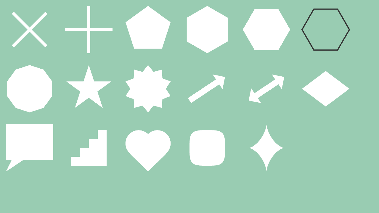
Shape2D::Cross(80, 10, Vec2{ 100, 100 }).draw();
Shape2D::Plus(80, 10, Vec2{ 300, 100 }).draw();
Shape2D::Pentagon(80, Vec2{ 500, 100 }).draw();
Shape2D::Hexagon(80, Vec2{ 700, 100 }).draw();
Shape2D::Hexagon(80, Vec2{ 900, 100 }, 30_deg).draw();
Shape2D::Hexagon(80, Vec2{ 1100, 100 }, 30_deg).drawFrame(4, ColorF{ 0.2 });
Shape2D::Ngon(10, 80, Vec2{ 100, 300 }).draw();
Shape2D::Star(80, Vec2{ 300, 300 }).draw();
Shape2D::NStar(10, 80, 60, Vec2{ 500, 300 }).draw();
Shape2D::Arrow(Line{ 640, 340, 760, 260 }, 20, Vec2{ 40, 30 }).draw();
Shape2D::DoubleHeadedArrow(Line{ 840, 340, 960, 260 }, 20, Vec2{ 40, 30 }).draw();
Shape2D::Rhombus(160, 120, Vec2{ 1100, 300 }).draw();
Shape2D::RectBalloon(RectF{ 20, 420, 160, 120 }, Vec2{ 20, 580 }, 0.5).draw();
Shape2D::Stairs(Vec2{ 360, 560 }, 120, 120, 4).draw();
Shape2D::Heart(80, Vec2{ 500, 500 }).draw();
Shape2D::Squircle(60, Vec2{ 700, 500 }, 64).draw();
Shape2D::Astroid(Vec2{ 900, 500 }, 60, 80).draw();
}
}
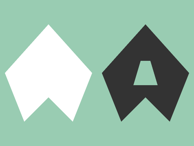
26.16 Free Polygon
- Arbitrary polygons are represented by
Polygon
Polygon can be created as follows:
- Must have at least 3 vertices, with the outer perimeter specified clockwise and holes specified counterclockwise
| Code |
Description |
Polygon{ vertex0, vertex1, ... } |
Creates a polygon |
Polygon{ Array<Vec2>{ ... } } |
Creates a polygon |
Polygon{ Array<Vec2>{ ... }, Array<Array<Vec2>>{ ... } } |
Creates a polygon with holes |
Polygon{ Shape2D } |
Creates a polygon from Shape2D |
circle.asPolygon(quality) |
Converts a circle to a polygon |
ellipse.asPolygon(quality) |
Converts an ellipse to a polygon |
rect.asPolygon() |
Converts a rectangle (Rect or RectF) to a polygon |
roundRect.asPolygon() |
Converts a rounded rectangle (RoundRect) to a polygon |
triangle.asPolygon() |
Converts a triangle (Triangle) to a polygon |
quad.asPolygon() |
Converts a quadrilateral (Quad) to a polygon |
shape2D.asPolygon() |
Converts Shape2D to a polygon |
- Creating
Polygon objects has runtime costs for memory allocation and triangulation calculations
- In particular, those with many vertices should be avoided inside loops.
- To draw a polygon, use
Polygon's .draw()
| Code |
Description |
.draw(color) |
Draws a polygon |
.draw(X offset, Y offset, color) |
Draws a polygon |
.draw(offset, color) |
Draws a polygon |
- To draw a polygon outline, use
Polygon's .drawFrame()
| Code |
Description |
.drawFrame(thickness, color) |
Draws a polygon outline |
.drawFrame(X offset, Y offset, thickness, color) |
Draws a polygon outline |
.drawFrame(offset, thickness, color) |
Draws a polygon outline |
# include <Siv3D.hpp>

void Main()
{
	Scene::SetBackground(ColorF{ 0.6, 0.8, 0.7 });

	// Polygon
	const Polygon polygon1
	{
		Vec2{ 200, 100 }, Vec2{ 380, 300 }, Vec2{ 300, 500 }, Vec2{ 200, 400 }, Vec2{ 100, 500 }, Vec2{ 20, 300 }
	};

	// Polygon with hole
	const Polygon polygon2
	{
		// Outer perimeter
		{ Vec2{ 600, 100 }, Vec2{ 780, 300 }, Vec2{ 700, 500 }, Vec2{ 600, 400 }, Vec2{ 500, 500 }, Vec2{ 420, 300 } },

		// Hole
		{ { Vec2{ 620, 250 }, Vec2{ 580, 250 }, Vec2{ 550, 350 }, Vec2{ 650, 350 } } }
	};

	while (System::Update())
	{
		polygon1.draw();
		polygon2.draw(ColorF{ 0.2 });
	}
}
- If you want to draw shapes with less runtime cost than
Polygon, use lower-level classes like Shape2D or Buffer2D
- With
Shape2D, you need to prepare index arrays in addition to vertex arrays yourself
- With
Buffer2D, you also need to prepare UV coordinates for texture mapping
- Neither is covered in this chapter
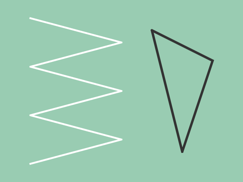
26.17 Continuous Line Segments
- Continuous line segments are represented by
LineString
LineString can be created as follows:
| Code |
Description |
LineString{ vertex0, vertex1, ... } |
Creates continuous line segments |
LineString{ Array<Point>{ ... } } |
Creates continuous line segments |
LineString{ Array<Vec2>{ ... } } |
Creates continuous line segments |
- To draw continuous line segments, use
LineString's .draw() or .drawClosed()
.draw() does not connect the end point to the start point.drawClosed() connects the end point to the start point
| Code |
Description |
.draw(thickness, color) |
Draws continuous line segments |
.draw(LineStyle::RoundCap, thickness, color) |
Draws continuous line segments with rounded ends |
.drawClosed(thickness, color) |
Draws continuous line segments (connecting end to start) |
# include <Siv3D.hpp>

void Main()
{
	Scene::SetBackground(ColorF{ 0.6, 0.8, 0.7 });

	const LineString ls1
	{
		Vec2{ 100, 60 }, Vec2{ 400, 140 },
		Vec2{ 100, 220 }, Vec2{ 400, 300 },
		Vec2{ 100, 380 }, Vec2{ 400, 460 },
		Vec2{ 100, 540 }
	};

	const LineString ls2
	{
		Vec2{ 500, 100 }, Vec2{ 700, 200 },
		Vec2{ 600, 500 },
	};

	while (System::Update())
	{
		ls1.draw(6);

		ls2.drawClosed(8, ColorF{ 0.2 });
	}
}
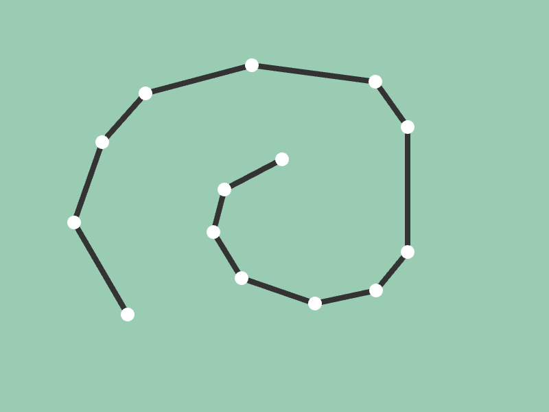
LineString is essentially Array<Vec2>- Array-like operations are possible
# include <Siv3D.hpp>

void Main()
{
	Scene::SetBackground(ColorF{ 0.6, 0.8, 0.7 });

	LineString points;

	while (System::Update())
	{
		// If left-clicked
		if (MouseL.down())
		{
			// Add a point
			points << Cursor::Pos();
		}

		// Draw continuous line segments
		points.draw(8, ColorF{ 0.2 });

		// For each point
		for (const auto& point : points)
		{
			// Draw a circle
			point.asCircle(10).draw();
		}
	}
}
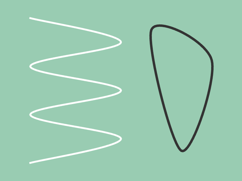
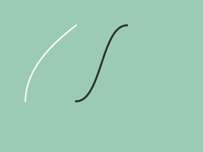
26.18 Spline Curves
- Catmull-Rom spline curves are represented by
Spline2D
- Catmull-Rom spline curves always pass through the specified control points
Spline2D can be created as follows:
- Specifying
CloseRing::Yes creates a closed ring connecting the end to the start
| Code |
Description |
Spline2D{ Array<Vec2>{ ... } } |
Creates a Catmull-Rom spline curve |
Spline2D{ LineString{ ... } } |
Creates a Catmull-Rom spline curve |
Spline2D{ Array<Vec2>{ ... }, CloseRing::Yes } |
Creates a Catmull-Rom spline curve (ring) |
- To draw a spline curve, use
Spline2D's .draw()
| Code |
Description |
.draw(color, quality = 24) |
Draws a spline curve |
.draw(thickness, color, quality = 24) |
Draws a spline curve |
.draw(LineStyle::RoundCap, thickness, color, quality = 24) |
Draws a spline curve with rounded ends |
# include <Siv3D.hpp>

void Main()
{
	Scene::SetBackground(ColorF{ 0.6, 0.8, 0.7 });

	const LineString ls
	{
		Vec2{ 100, 60 }, Vec2{ 400, 140 },
		Vec2{ 100, 220 }, Vec2{ 400, 300 },
		Vec2{ 100, 380 }, Vec2{ 400, 460 },
		Vec2{ 100, 540 }
	};

	const Spline2D spline1{ ls };

	const Spline2D spline2
	{
		{ Vec2{ 500, 100 }, Vec2{ 700, 200 }, Vec2{ 600, 500 } },
		CloseRing::Yes
	};

	while (System::Update())
	{
		spline1.draw(6);

		spline2.draw(8, ColorF{ 0.2 });
	}
}
26.19 Bezier Curves
- Quadratic Bezier curves are represented by
Bezier2, and cubic Bezier curves by Bezier3
- Bezier curves can be created as follows:
| Code |
Description |
Bezier2{ start, control point, end } |
Creates a quadratic Bezier curve |
Bezier3{ start, control point 1, control point 2, end } |
Creates a cubic Bezier curve |
- To draw a Bezier curve, use
Bezier2 or Bezier3's .draw()
| Code |
Description |
.draw(color, quality = 24) |
Draws a Bezier curve |
.draw(thickness, color, quality = 24) |
Draws a Bezier curve |
.draw(LineStyle::RoundCap, thickness, color, quality = 24) |
Draws a Bezier curve with rounded ends |
# include <Siv3D.hpp>

void Main()
{
	Scene::SetBackground(ColorF{ 0.6, 0.8, 0.7 });

	while (System::Update())
	{
		// Quadratic Bezier curve
		Bezier2{ Vec2{ 100, 400 }, Vec2{ 100, 250 }, Vec2{ 300, 100 } }.draw(6);

		// Cubic Bezier curve
		Bezier3{ Vec2{ 300, 400 }, Vec2{ 400, 400 }, Vec2{ 400, 100 }, Vec2{ 500, 100 }}.draw(8, ColorF{ 0.2 });
	}
}
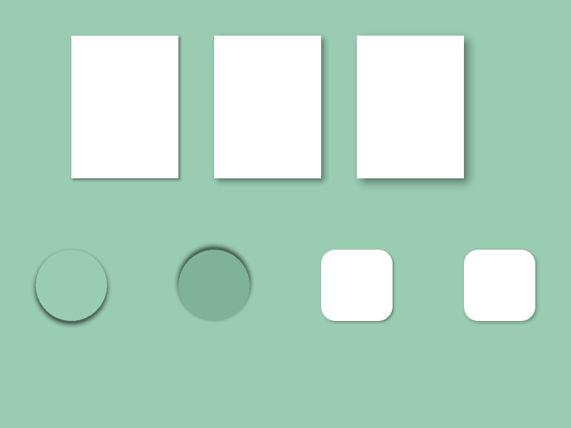
26.20 Shape Shadows
Circle, Rect, RectF, and RoundRect have a .drawShadow() member function to draw shadows
- The first argument specifies the shadow position offset, the second argument the blur size, the third argument the shadow size offset, and the fourth argument the shadow color
- Since shadows fill areas that would be hidden by the shape, you need to draw the shape on top after drawing the shadow
| Code |
Description |
.drawShadow(shadow position offset, blur size, shadow size offset, shadow color) |
Draws a shadow for shapes (Circle, Rect, RectF, RoundRect) |
- Since
.drawShadow() returns a reference to the shape itself, you can chain .draw() after it
# include <Siv3D.hpp>

void Main()
{
	Scene::SetBackground(ColorF{ 0.6, 0.8, 0.7 });

	while (System::Update())
	{
		Rect{ 100, 50, 150, 200 }
			.drawShadow(Vec2{ 2, 2 }, 8, 1)
			.draw();

		Rect{ 300, 50, 150, 200 }
			.drawShadow(Vec2{ 4, 4 }, 16, 1.5)
			.draw();

		Rect{ 500, 50, 150, 200 }
			.drawShadow(Vec2{ 6, 6 }, 24, 2)
			.draw();

		Circle{ 100, 400, 50 }
			.drawShadow(Vec2{ 0, 4 }, 10, 3)
			.draw(ColorF{ 0.6, 0.8, 0.7 });

		Circle{ 300, 400, 50 }
			.drawShadow(Vec2{ 0, -4 }, 10, 3)
			.draw(ColorF{ 0.5, 0.7, 0.6 });

		RoundRect{ 450, 350, 100, 100, 20 }
			.drawShadow(Vec2{ 2, 2 }, 8, 0)
			.draw();

		RoundRect{ 650, 350, 100, 100, 20 }
			.drawShadow(Vec2{ 2, 2 }, 12, 0)
			.draw();
	}
}
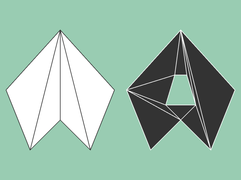
26.21 Polygon Wireframe Display
Polygon can display wireframes with .drawWireframe()
- Wireframe display draws all edges of the triangles that make up the polygon
| Code |
Description |
.drawWireframe(thickness, color) |
Draws a polygon wireframe |
# include <Siv3D.hpp>

void Main()
{
	Scene::SetBackground(ColorF{ 0.6, 0.8, 0.7 });

	const Polygon polygon1
	{
		Vec2{ 200, 100 }, Vec2{ 380, 300 }, Vec2{ 300, 500 }, Vec2{ 200, 400 }, Vec2{ 100, 500 }, Vec2{ 20, 300 }
	};

	const Polygon polygon2
	{
		{ Vec2{ 600, 100 }, Vec2{ 780, 300 }, Vec2{ 700, 500 }, Vec2{ 600, 400 }, Vec2{ 500, 500 }, Vec2{ 420, 300 } },
		{ { Vec2{ 620, 250 }, Vec2{ 580, 250 }, Vec2{ 550, 350 }, Vec2{ 650, 350 } } }
	};

	while (System::Update())
	{
		polygon1.draw();
		polygon1.drawWireframe(2, ColorF{ 0.2 });

		polygon2.draw(ColorF{ 0.2 });
		polygon2.drawWireframe(2);
	}
}