48. 2D Render States
Learn how to customize 2D rendering settings (render state) to achieve various screen effects.
48.1 Overview of 2D Render States
- In 2D rendering, you can modify the following settings:
48.1.1 Color Multiplication
- When drawing shapes or textures, RGBA components are multiplied by the original colors during rendering
- How to set this using
ScopedColorMul2Dis explained in 48.3
48.1.2 Color Addition
- When drawing shapes or textures, RGBA components are added to or subtracted from the original colors during rendering
- How to set this using
ScopedColorAdd2Dis explained in 48.4
48.1.3 Blend State
- Sets how the destination pixel colors are combined with the colors being drawn
- How to set this using
BlendStateand apply it withScopedRenderStates2Dis explained in 48.7
48.1.4 Sampler State
- Sets the interpolation method when textures are scaled up or down for rendering
- Sets how to handle UV coordinates that exceed the 0.0-1.0 range
- How to set this using
SamplerStateand apply it withScopedRenderStates2Dis explained in 48.8 and 48.9
48.1.5 Rasterizer State
- Sets wireframe display mode
- Sets scissor rectangle
- Sets whether to ignore (cull) clockwise or counter-clockwise triangles
- How to set this using
RasterizerStateand apply it withScopedRenderStates2Dis explained in 48.10 to 48.12
48.1.6 Viewport
- Changes the drawing area
- How to set this using
ScopedViewport2Dis explained in 48.13
48.2 How Scoped~ Works
- In this chapter, classes with names beginning with
Scoped~will appear:
| Code | Description |
|---|---|
ScopedColorMul2D |
Multiplies colors during drawing |
ScopedColorAdd2D |
Adds colors during drawing |
ScopedRenderStates2D |
Changes render state during 2D drawing |
ScopedViewport2D |
Changes the drawing area |
- In source code, these classes may appear to have no effect because you create objects of these classes without using the variables
- In reality, the constructor sets the passed settings to the engine, and when the object is destroyed (when the scope ends), the destructor restores the previous settings
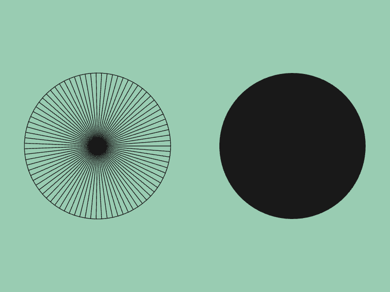
- Let's confirm how
ScopedRenderStates2Dworks with the following sample code- The first circle is drawn in wireframe display mode, and the second circle is drawn in normal drawing mode
# include <Siv3D.hpp>

void Main()
{
	Scene::SetBackground(ColorF{ 0.6, 0.8, 0.7 });

	while (System::Update())
	{
		{
			// Change render state (also save the previous state)
			const ScopedRenderStates2D rasterizer{ RasterizerState::WireframeCullNone };

			Circle{ 200, 300, 150 }.draw(ColorF{ 0.1 });

		} // Here the rasterizer destructor is called and restores the render state to the previous state

		Circle{ 600, 300, 150 }.draw(ColorF{ 0.1 });
	}
}
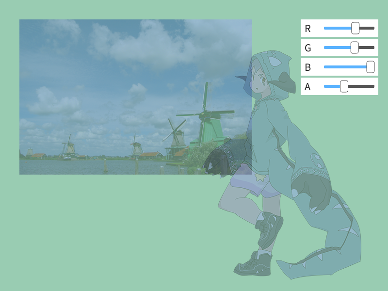
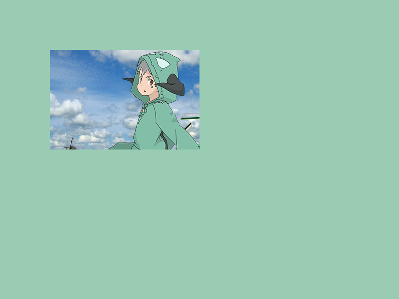
48.3 Color Multiplication for Drawing
- To multiply RGBA components when drawing images or shapes, set the values you want to multiply in the constructor of a
ScopedColorMul2Dobject - While that object is valid, the drawing RGBA values are multiplied
- The default value is
ColorF{ 1.0, 1.0, 1.0, 1.0 } - You can also set the multiplication color by passing a color to
Texture's.draw()(Tutorial 31.12).ScopedColorMul2Dperforms this setting collectively
# include <Siv3D.hpp>

void Main()
{
	Scene::SetBackground(ColorF{ 0.6, 0.8, 0.7 });

	const Texture texture1{ U"example/windmill.png" };
	const Texture texture2{ U"example/siv3d-kun.png" };
	ColorF color{ 1.0, 1.0, 1.0, 1.0 };

	while (System::Update())
	{
		{
			// Set to multiply colors during drawing
			const ScopedColorMul2D colorMul{ color };

			texture1.draw(40, 40);
			texture2.draw(400, 100);
		}

		SimpleGUI::Slider(U"R", color.r, Vec2{ 620, 40 }, 40);
		SimpleGUI::Slider(U"G", color.g, Vec2{ 620, 80 }, 40);
		SimpleGUI::Slider(U"B", color.b, Vec2{ 620, 120 }, 40);
		SimpleGUI::Slider(U"A", color.a, Vec2{ 620, 160 }, 40);
	}
}
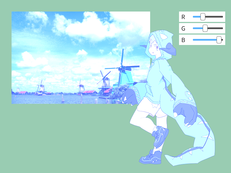
48.4 Color Addition for Drawing
- To add RGBA components when drawing images or shapes, set the values you want to add in the constructor of a
ScopedColorAdd2Dobject - While that object is valid, RGBA values are added to the drawing
- The default value is
ColorF{ 0.0, 0.0, 0.0, 0.0 } - Subtraction is also possible by setting negative values
- This is applied after the color multiplication from 48.3
# include <Siv3D.hpp>

void Main()
{
	Scene::SetBackground(ColorF{ 0.6, 0.8, 0.7 });

	const Texture texture1{ U"example/windmill.png" };
	const Texture texture2{ U"example/siv3d-kun.png" };
	ColorF color{ 0.0, 0.0, 0.0, 0.0 };

	while (System::Update())
	{
		{
			// Set to add colors during drawing
			const ScopedColorAdd2D colorAdd{ color };

			texture1.draw(40, 40);
			texture2.draw(400, 100);
		}

		SimpleGUI::Slider(U"R", color.r, Vec2{ 620, 40 }, 40);
		SimpleGUI::Slider(U"G", color.g, Vec2{ 620, 80 }, 40);
		SimpleGUI::Slider(U"B", color.b, Vec2{ 620, 120 }, 40);
	}
}
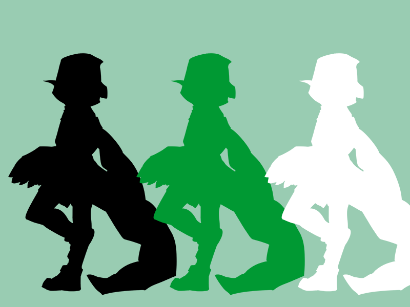
48.5 Solid Color Texture Drawing
- By adding color using
ScopedColorAdd2Dto a texture drawn black with.draw(ColorF{ 0.0 }), you can draw it in a solid color
# include <Siv3D.hpp>

void Main()
{
	Scene::SetBackground(ColorF{ 0.6, 0.8, 0.7 });
	const Texture texture{ U"example/siv3d-kun.png" };

	while (System::Update())
	{
		// Fill with black
		{
			texture.draw(0, 100, ColorF{ 0.0 });
		}

		// Fill with green
		{
			const ScopedColorAdd2D color{ 0.0, 0.6, 0.2 };
			texture.draw(250, 100, ColorF{ 0.0 });
		}

		// Fill with white
		{
			const ScopedColorAdd2D color{ 1.0, 1.0, 1.0 };
			texture.draw(500, 100, ColorF{ 0.0 });
		}
	}
}
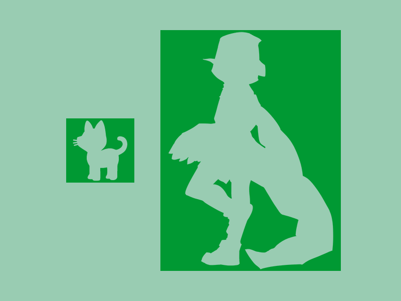
48.6 Transparency Inversion
- By setting transparent parts to alpha value
0.0and non-transparent parts to alpha value-1.0with.draw(ColorF{ 0.0, -1.0 }), then adding alpha value1.0usingScopedColorAdd2D, you can invert the transparent and non-transparent parts
# include <Siv3D.hpp>

void Main()
{
	Scene::SetBackground(ColorF{ 0.6, 0.8, 0.7 });
	const Texture emoji{ U"🐈"_emoji };
	const Texture texture{ U"example/siv3d-kun.png" };

	while (System::Update())
	{
		{
			const ScopedColorAdd2D color{ 0.0, 0.6, 0.2, 1.0 };
			emoji.drawAt(200, 300, ColorF{ 0.0, -1.0 });
			texture.drawAt(500, 300, ColorF{ 0.0, -1.0 });
		}
	}
}
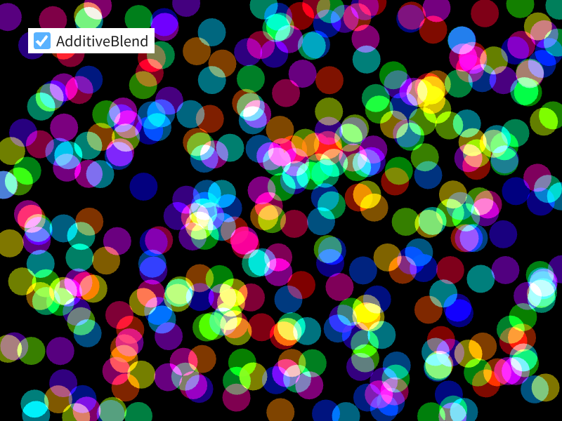
48.7 Additive Blending
- When you pass
BlendState::Additiveto the constructor of aScopedRenderStates2Dobject, shapes and images are drawn with additive blending while that object is valid - In additive blending, RGB components are added to the background color during drawing, so overlapping areas become brighter
# include <Siv3D.hpp>

void Main()
{
	Scene::SetBackground(ColorF{ 0.0 });

	Array<Vec2> points;

	for (int32 i = 0; i < 400; ++i)
	{
		points << RandomVec2(Scene::Rect());
	}

	// Whether to enable additive blending
	bool additiveBlend = true;

	while (System::Update())
	{
		if (additiveBlend)
		{
			// Additive blending enabled
			const ScopedRenderStates2D blend{ BlendState::Additive };

			for (const auto& point : points)
			{
				Circle{ point, 20 }.draw(HSV{ (point.y * 100 + point.x * 100), 0.5 });
			}
		}
		else
		{
			// Normal blending
			for (const auto& point : points)
			{
				Circle{ point, 20 }.draw(HSV{ (point.y * 100 + point.x * 100), 0.5 });
			}
		}

		SimpleGUI::CheckBox(additiveBlend, U"AdditiveBlend", Vec2{ 40, 40 });
	}
}
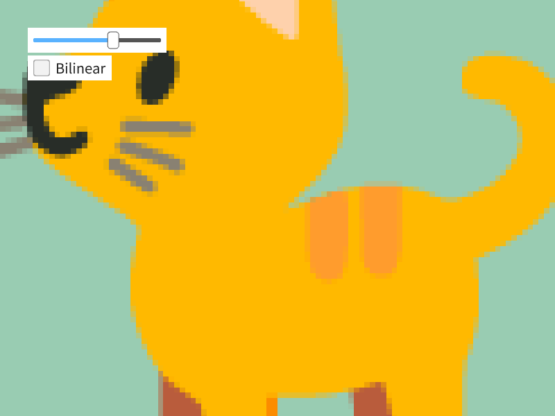
48.8 Texture Scaling Filter
- There are two interpolation methods for scaling textures:
| Setting Name | Description |
|---|---|
| Linear | Bilinear interpolation (default for 2D drawing) |
| Nearest | Nearest neighbor interpolation |
- By default, colors are interpolated using bilinear interpolation
- When you want to scale up textures while maintaining the pixel feel, use Nearest
- Set the sampler state
SamplerState::ClampNearestinScopedRenderStates2D
- Set the sampler state
# include <Siv3D.hpp>

void Main()
{
	const Texture texture{ U"🐈"_emoji };
	bool bilinear = true;
	double scale = 1.0;

	while (System::Update())
	{
		if (bilinear)
		{
			// Bilinear interpolation (default)
			texture.scaled(scale).drawAt(400, 300);
		}
		else
		{
			// Nearest neighbor interpolation
			const ScopedRenderStates2D sampler{ SamplerState::ClampNearest };
			texture.scaled(scale).drawAt(400, 300);
		}

		SimpleGUI::Slider(scale, 0.5, 12.0, Vec2{ 40, 40 }, 200);
		SimpleGUI::CheckBox(bilinear, U"Bilinear", Vec2{ 40, 80 });
	}
}
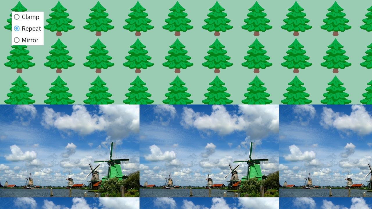
48.9 Texture Tiling
- You can customize how UV coordinates are handled when they exceed the 0.0-1.0 range during texture drawing
| Setting Name | Description |
|---|---|
| Clamp | Draw the edge colors of the texture as is (default for 2D drawing) |
| Repeat | Draw so that the edge colors of the texture continue from the opposite edge |
| Mirror | Draw so that the edge colors of the texture continue mirrored from the opposite edge |
- The default is Clamp, combined with the default texture filtering value Linear as
SamplerState::ClampLinear - Also refer to Tutorial 31.18 for texture repeat drawing
#include <Siv3D.hpp>

void Draw(const Texture& tree, const Texture& windmill)
{
	tree.mapped(1280, 360).draw();
	windmill.mapped(1280, 360).draw(0, 360);
}

void Main()
{
	Window::Resize(1280, 720);
	Scene::SetBackground(ColorF{ 0.6, 0.8, 0.7 });

	const Texture tree{ U"🌲"_emoji };
	const Texture windmill{ U"example/windmill.png" };

	size_t option = 0;

	while (System::Update())
	{
		if (option == 0)
		{
			// Set to clamp when UV coordinates exceed the 0.0-1.0 range
			const ScopedRenderStates2D sampler{ SamplerState::ClampLinear };
			Draw(tree, windmill);
		}
		else if (option == 1)
		{
			// Set to repeat mapping when UV coordinates exceed the 0.0-1.0 range
			const ScopedRenderStates2D sampler{ SamplerState::RepeatLinear };
			Draw(tree, windmill);
		}
		else if (option == 2)
		{
			// Set to mirror when UV coordinates exceed the 0.0-1.0 range
			const ScopedRenderStates2D sampler{ SamplerState::MirrorLinear };
			Draw(tree, windmill);
		}

		SimpleGUI::RadioButtons(option, { U"Clamp", U"Repeat", U"Mirror" }, Vec2{ 40, 40 });
	}
}
48.10 Wireframe Display
- There is a mode that draws only the wireframes of triangles that make up shapes and images
| Setting Name | Description |
|---|---|
| Wireframe | Wireframe display |
| Solid | Normal drawing mode (default for 2D drawing) |
- When you pass
RasterizerState::WireframeCullNoneto the constructor of aScopedRenderStates2Dobject, wireframe display mode is enabled while that object is valid - Wireframe display is not available in the Web version
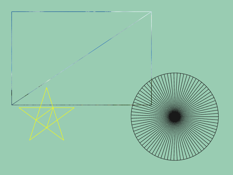
# include <Siv3D.hpp>

void Main()
{
	Scene::SetBackground(ColorF{ 0.6, 0.8, 0.7 });

	const Texture texture{ U"example/windmill.png" };

	while (System::Update())
	{
		{
			// Set to wireframe display mode
			const ScopedRenderStates2D rasterizer{ RasterizerState::WireframeCullNone };

			texture.draw(40, 40);

			Circle{ 600, 400, 150 }.draw(ColorF{ 0.1 });

			Shape2D::Star(100, Vec2{ 160, 400 }).draw(Palette::Yellow);
		}
	}
}
48.11 Scissor Rectangle
- Setting a scissor rectangle allows you to prevent drawing outside a rectangular area
- Register the scissor rectangle area with
Graphics2D::SetScissorRect(), and apply aRasterizerStatewith.scissorEnableset totrueusingScopedRenderStates2Dto enable the scissor rectangle
#include <Siv3D.hpp>

void Main()
{
	Scene::SetBackground(ColorF{ 0.6, 0.8, 0.7 });

	const Texture texture1{ U"example/windmill.png" };
	const Texture texture2{ U"example/siv3d-kun.png" };

	// Register the scissor rectangle range
	Graphics2D::SetScissorRect(Rect{ 100, 100, 300, 200 });

	while (System::Update())
	{
		{
			RasterizerState rs = RasterizerState::Default2D;
			rs.scissorEnable = true;

			// Enable scissor rectangle
			const ScopedRenderStates2D rasterizer{ rs };

			texture1.draw(40, 40);
			texture2.draw(160, 100);
		}
	}
}
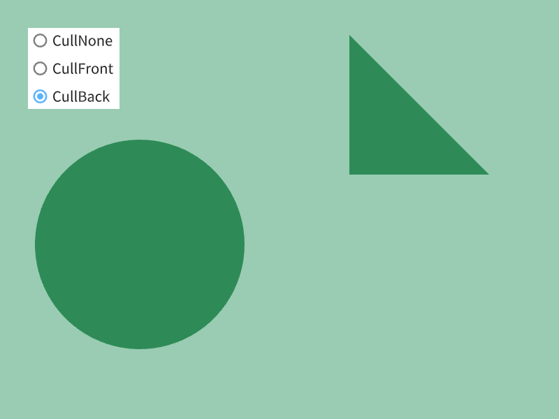
48.12 Culling
- You can set whether to ignore (cull) clockwise (front-facing) triangles and counter-clockwise (back-facing) triangles
| Setting Name | Description |
|---|---|
| CullNone | No culling (default for 2D drawing) |
| CullFront | Cull clockwise (front-facing) triangles |
| CullBack | Cull counter-clockwise (back-facing) triangles |
- When you pass
RasterizerState::SolidCullBackto the constructor of aScopedRenderStates2Dobject, counter-clockwise triangles are culled while that object is valid - Normally, back-facing triangles do not occur unless you explicitly specify counter-clockwise vertices
# include <Siv3D.hpp>

void Draw()
{
	// Circle (all triangles are front-facing)
	Circle{ 200, 350, 150 }.draw(Palette::Seagreen);

	// Clockwise (front-facing) triangle
	Triangle{ 500, 50, 700, 250, 500, 250 }.draw(Palette::Seagreen);

	// Counter-clockwise (back-facing) triangle
	Triangle{ 500, 300, 500, 500, 700, 500, }.draw(Palette::Seagreen);
}

void Main()
{
	Scene::SetBackground(ColorF{ 0.6, 0.8, 0.7 });

	size_t option = 0;

	while (System::Update())
	{
		if (option == 0)
		{
			// No culling
			const ScopedRenderStates2D rasterizer{ RasterizerState::SolidCullNone };
			Draw();
		}
		else if (option == 1)
		{
			// Cull clockwise triangles
			const ScopedRenderStates2D rasterizer{ RasterizerState::SolidCullFront };
			Draw();

		}
		else if (option == 2)
		{
			// Cull counter-clockwise triangles
			const ScopedRenderStates2D rasterizer{ RasterizerState::SolidCullBack };
			Draw();
		}

		SimpleGUI::RadioButtons(option, { U"CullNone", U"CullFront", U"CullBack" }, Vec2{ 40, 40 });
	}
}
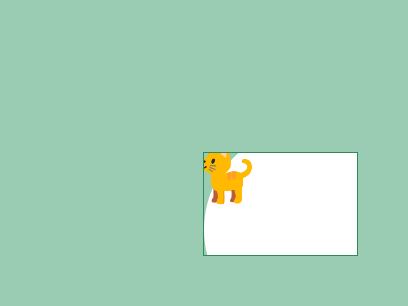
48.13 Viewport
- Creating a
ScopedViewport2Dobject allows you to create a virtual scene within the scene and define a new drawing area - During drawing, the top-left of the viewport rectangle becomes the (0, 0) drawing coordinate, and anything that extends outside the rectangle is not drawn
- Viewport only affects drawing coordinates. If you want to move the mouse cursor coordinates to match the viewport, combine it with
Transformer2Dwhich is learned in Tutorial 49
# include <Siv3D.hpp>

void Main()
{
	Scene::SetBackground(ColorF{ 0.6, 0.8, 0.7 });

	const Texture cat{ U"🐈"_emoji };

	const Rect viewportRect{ 400, 300, 300, 200 };

	while (System::Update())
	{
		{
			// Apply viewport
			const ScopedViewport2D viewport{ viewportRect };

			Circle{ 200, 150, 200 }.draw();

			cat.drawAt(40, 40);
		}

		viewportRect.drawFrame(0, 2, Palette::Seagreen);
	}
}